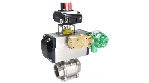
A valve actuator is the component that moves a valve from one position to another in response to a signal. Its presence converts a manually operated valve into an automated one, enabling remote control, process integration, and defined fail-safe behaviour that is impossible to achieve with a handwheel alone.
Actuator selection is not simply a matter of choosing between pneumatic and electric. The torque or force required to operate the valve, the number of operating cycles per day, the available utilities, the fail-safe requirement, the operating environment, the need for intermediate positioning versus simple on/off control, and the level of diagnostic integration required all influence the right choice.
This guide covers the main actuator types, the design considerations that distinguish them, the auxiliary components that complete a functioning actuated valve assembly, and the criteria that determine which approach suits a given duty.
Why Automate a Valve?
Manual valve operation requires a person to be physically present at the valve at the moment of operation. In most industrial process environments, this is not practical or safe.
- Remote operation - The valve can be opened, closed, or modulated from a control room, SCADA system, or PLC without anyone approaching it. This is essential in hazardous areas, confined spaces, and high-temperature or high-pressure environments where proximity during operation presents a risk.
- Repeatable, consistent positioning - A manual operator produces variable torque and variable positioning. An actuator delivers the same force at the same control signal every time, removing operator variability from the process.
- Defined fail-safe behaviour - A manually operated valve stays in whatever position it was last set. An actuated valve with a spring-return mechanism moves to a defined safe position on loss of power or signal, without human intervention.
- Process integration - An actuated valve can receive a 4-20mA or digital control signal from a controller, PLC, or DCS, and return a position feedback signal confirming its actual position, enabling closed-loop control, interlock functions, and remote monitoring.
Actuator Movement: Quarter-Turn vs Linear
Before considering the power source, the correct motion type must be matched to the valve being actuated.
Quarter-turn actuators produce 90 degrees of rotational output. They are used on ball valves, butterfly valves, and plug valves, all of which open and close with a 90-degree rotation. Rack-and-pinion and scotch-yoke are the two principal mechanical designs for quarter-turn pneumatic actuators; electric quarter-turn actuators use a motor with a gearbox to produce the same output.
Linear actuators produce a straight-line push or pull motion. They are used on globe valves, gate valves, diaphragm valves, pinch valves, and angle seat valves where the closure element moves perpendicular to the flow path. Pneumatic linear actuators use either a piston-cylinder or a diaphragm to generate linear force; electric linear actuators use a motor driving a lead screw.
Matching the actuator motion type to the valve design is non-negotiable. A quarter-turn actuator cannot be connected to a globe valve, and a linear actuator cannot be connected to a ball valve without a conversion mechanism.
Pneumatic Actuators
Pneumatic actuators use compressed air as their power source. They are the most widely used actuator type in industrial process automation, preferred for their high power-to-weight ratio, inherent fail-safe capability, tolerance of harsh environments, and simple maintenance.
Rack-and-pinion actuators
The rack-and-pinion design uses a piston driven by compressed air. As the piston moves linearly within a cylinder, a rack on the piston engages a pinion gear on the output shaft, converting linear motion to rotation. Rack-and-pinion actuators are compact and light for their output torque, and are the standard choice for ball and butterfly valves up to medium pipe sizes where cost efficiency is important. The torque output varies slightly across the stroke: slightly lower at mid-stroke than at the start and end positions, which is a consideration in throttling applications but not significant for most on/off duties.
Scotch-yoke actuators
Scotch-yoke actuators use a piston and cylinder, but the piston rod connects to a slotted yoke that converts linear motion to rotation via an offset pin. The geometry means torque output is highest at the beginning and end of the stroke and lowest at mid-stroke. This characteristic matches the torque curve of many valve types, including ball valves, which require highest torque at start of opening (breakout) and at end of closing (seating). Scotch-yoke actuators are the preferred choice for larger bore valves and high-torque applications.
Spring-return vs double-acting
This is one of the most important decisions in actuator selection, and it directly determines the valve's fail-safe behaviour.
Spring-return (single-acting) actuators use compressed air to drive the actuator in one direction and a set of internal springs to return it to its default position when the air supply is vented or lost. The valve therefore has a defined fail-safe position, either fully open (fail-open) or fully closed (fail-closed), reached passively if the air supply is interrupted or if a safety system commands the valve to its safe position. Spring-return actuators are larger and heavier than equivalent double-acting designs because they must overcome the spring force in addition to operating the valve.
Double-acting actuators use compressed air to drive the actuator in both directions. There is no spring return and no inherent fail-safe position: if the air supply or signal is lost, the valve remains in its last commanded position. Achieving a defined fail-safe position with a double-acting actuator requires either a spring-return module, an accumulator tank, or an independent return mechanism. Double-acting actuators are more compact and require less supply pressure, and are preferred for large valves where the spring size required for spring-return becomes impractical.
Electric Actuators
Electric actuators use a reversing motor and gearbox to open, close, or position a valve in response to an electrical signal. They are the natural choice where compressed air is not available, where the operating cycle is infrequent, or where precise intermediate positioning is required.
The two main configurations are quarter-turn and multi-turn. Quarter-turn electric actuators produce 90-degree rotational output and are used on ball and butterfly valves. They typically include limit switches to stop the motor at end-of-travel, a manual override handwheel for use during power loss or maintenance, and position feedback via a potentiometer or encoder. Multi-turn actuators are used on gate, globe, and other valves where full travel requires more than a single quarter-turn of the output shaft.
For modulating duties, electric actuators can be paired with a positioner. The positioner accepts a 4-20mA or 0-10V control signal and continuously compares the demanded valve position against actual position via a feedback sensor, driving the motor to close any gap. This makes positioner-equipped electric actuators the preferred choice for continuous flow control, where the valve must hold accurately at any point in its travel rather than simply opening or closing fully.
Measure Monitor Control supply actuated valve packages incorporating electric actuators with integrated positioners, real-time position feedback, and remote diagnostics for predictive maintenance. Fail-safe options are available using battery backup or stored energy capacitors, which drive the valve to its defined safe position on loss of mains power.
Hydraulic Actuators
Hydraulic actuators use pressurised hydraulic fluid rather than compressed air or electricity. They develop very high forces and torques from a compact body, making them the preferred choice for large bore, high-pressure valves where pneumatic actuators would require impractically large cylinder diameters or very high supply pressures. Hydraulic actuators are most common in pipeline and subsea applications and large isolation valves on oil and gas facilities. They require a hydraulic power unit (HPU) to generate and maintain hydraulic pressure, adding cost and complexity compared to pneumatic or electric alternatives.
The Complete Actuated Valve Assembly
An actuator mounted on a valve body is only one part of a functional automated valve. A complete assembly typically includes:
Solenoid pilot valves
Solenoid valves for this duty are available in 2/2 and 3/2 configurations, in brass or stainless steel, with ATEX, IECEx, and GOST EAC certification for hazardous area installation. The NADI range, available from Measure Monitor Control, covers temperatures down to -60°C for Arctic and cold climate duties.
Air preparation
Filter regulator installed upstream of the solenoid pilot valve ensures the actuator receives suitable quality air. Contaminated or wet air degrades actuator seals and reduces service life significantly.
Spool valves and pneumatic logic
Spool valves and air pilot operated valves provide the circuit logic. The Sitecna range, certified to IEC 61508 SIL 3, covers safety-rated pneumatic actuation circuit components including volume boosters for fast stroke times and quick exhaust valves for rapid closing response.
Position feedback and switchboxes
Confirming that a valve has actually reached its commanded position is essential for process control and safety interlock functions. Position feedback is provided by limit switches mounted in a switchbox on the actuator, which signal fully open and fully closed positions to the control system. Where partial stroke confirmation or continuous position feedback across the full stroke is required, positioners with analogue output replace simple limit switches. Measure Monitor Control supply actuated valve packages with integrated switchboxes and position sensors as standard options.
ATEX certification
ATEX and IECEx certification for the zone classification of the installation. Measure Monitor Control supply complete ATEX-certified actuated valve assemblies, built and tested before dispatch.
Torque and Force Sizing
An actuator that cannot generate sufficient torque to operate the valve under all expected conditions will fail to open or close reliably. Correct sizing is a fundamental requirement, not a detail.
Valve torque requirements vary with valve type, size, pressure differential, and the condition of seals and packing. The breakout torque, which is the torque required to start movement from the seated position, is typically the highest and must be the reference point for sizing, not the running torque. For ball and butterfly valves, manufacturers publish torque data at rated differential pressure; this data must be used, not estimated.
The actuator output torque must exceed the valve breakout torque by an adequate safety margin. A margin of 25% is commonly used as a minimum, with higher margins where the valve may be subject to elevated seating loads, sticky media, or extended periods between operations. For spring-return actuators, the spring torque that must be overcome on the air stroke reduces the net available torque, and the datasheet must be checked against the full valve requirement at both ends of stroke.
Key Selection Criteria
- Utility availability - Is compressed air available at sufficient pressure and quality? If not, electric is the default. If both are available, the duty cycle and positioning requirement determine which is more appropriate.
- Fail-safe requirement - What position must the valve reach on loss of power or signal? Spring-return pneumatic is the simplest and most reliable means of achieving a defined fail-safe position.
- On/off or modulating - Simple open/close duties suit pneumatic on/off actuation. Continuous modulating control suits electric actuation with a positioner, or a pneumatic actuator with a smart positioner.
- Operating cycle - High-cycle duties suit pneumatic actuators. Electric actuators have duty cycle ratings that restrict operations per hour; exceeding them causes motor overheating.
- Environment - For hazardous areas, ATEX-certified components are mandatory. For corrosive environments, stainless steel bodied components and IP65 or higher enclosures are appropriate.
- Safety integrity - For safety-instrumented functions, components must carry verified SIL capability ratings with documented FMEDA data. See the Measure Monitor Control guide to functional safety, IEC 61508 and SIL for a full explanation of the requirements.
Measure Monitor Control supply actuated valve packages as built and tested assemblies including pneumatic and electric actuated ball and butterfly valves, complete with solenoid pilot valves, position feedback, air preparation, ATEX certification, and all ancillaries. Contact the team to discuss the requirements for your application.