Most measurement techniques tell you what is happening at a single point. A strain gauge reports strain at the precise location where it is bonded. A transducer reports displacement at the point where it is mounted. If the event you are trying to capture happens somewhere else on the component, or if the deformation mode is distributed across a surface, point measurement leaves significant gaps in your understanding.
Digital Image Correlation fills those gaps. It is an optical, non-contact measurement technique that tracks deformation, strain, displacement, and motion across a full field of view, from every point on the surface being imaged simultaneously. No bonding, no contact, no risk of influencing the measurement by attaching a sensor to the structure.
This guide explains how DIC works, what distinguishes 2D and 3D systems, how to prepare a test correctly, what DIC is suited to measuring, and how to select the right system for your application.
What Is Digital Image Correlation?
Digital Image Correlation is a computational optical technique that compares digital images taken at different points in time or under different loading conditions, and calculates the displacement and strain fields that describe how the imaged surface has deformed between those states.
The technique was developed in the early 1980s at the University of South Carolina and has since become a standard tool in experimental mechanics research and industrial testing. It is referenced in major standards bodies including ASTM E2208, which provides guidance on the evaluation and qualification of optical non-contacting displacement measuring systems, and ISO 26203, which covers high strain rate tensile testing where full-field measurement is increasingly required.
The core principle is image tracking. The software divides the image into a grid of small subsets, each a small region of pixels containing a unique local texture. Between images taken at different states, the algorithm searches for the position of each subset in the new image by maximising a correlation coefficient. The displacement of each subset from its original position to its new position is the displacement at that point. By computing this for every subset across the image, the software generates a full-field displacement map. Differentiating the displacement field spatially gives the full-field strain map.
Why The Speckle Pattern Matters
DIC depends on each subset of the image having a unique, trackable texture. Smooth, uniform surfaces cannot be tracked because all subsets look the same. A random, high-contrast speckle pattern applied to the specimen surface provides the necessary texture.
The speckle pattern is typically applied by painting the surface with a white base coat and then applying small black speckles using spray paint, airbrush, or inkjet printing depending on the scale. The quality of the speckle pattern directly determines the accuracy of the DIC measurement.
- Speckle size - Speckles should be 3 to 5 pixels in diameter in the captured image. Too small and individual speckles are not clearly resolved. Too large and each subset contains too few speckles to provide a unique local signature.
- Random distribution - The pattern must be genuinely random. Regular or periodic patterns create ambiguity in the tracking algorithm because multiple positions look identical.
- Contrast - High contrast between white background and black speckles maximises the correlation signal and reduces noise.
- Durability - For tests involving large deformations, elevated temperatures, or extended duration, the pattern must remain adhered and intact throughout. Specialist high-temperature speckle methods are used for elevated temperature DIC. For micro-scale specimens, chemical etching, electron beam lithography, or photolithography can produce fine-scale patterns.
2D vs 3D DIC: Choosing the Right System
The choice between a 2D and a 3D DIC system is determined by the nature of the deformation being measured and the geometry of the test.
2D DIC
A 2D DIC system uses a single camera to image the specimen surface. It measures in-plane displacements and strains, meaning motion and deformation within the plane of the camera sensor. This is appropriate when the specimen surface is nominally flat and remains flat during the test, and when out-of-plane motion is either negligible or not of interest.
2D DIC systems are quick to install and require a simpler calibration process than stereo configurations.
The principal limitation of 2D DIC is that any out-of-plane motion introduces an apparent in-plane displacement error, because the camera cannot distinguish between the specimen moving closer to the lens and features actually becoming larger. This perspective error can be significant even for small out-of-plane displacements.
3D DIC
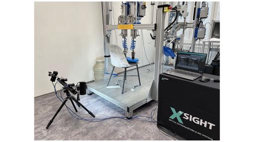
A 3D DIC system uses two cameras arranged at an angle to each other, forming a stereo pair. By combining the two views, the system reconstructs the three-dimensional position of every point on the specimen surface, in a process similar in principle to human binocular vision.
3D DIC systems cover applications including residual stress measurement, vibration analysis, strain concentration, deflection, three-dimensional motion, adhesion testing, extension and compression, and crack propagation tracking, at scales from millimetre-scale laboratory specimens to large structural elements in the field.
Camera Calibration
For DIC measurements to be metrologically valid, the cameras must be calibrated. Calibration establishes the relationship between pixel coordinates in the image and real-world coordinates in space, accounting for the camera's optical properties including focal length, principal point, and lens distortion.
For 2D systems, single camera calibration corrects for lens distortion and establishes the pixel-to-millimetre scale factor. For 3D stereo systems, calibration must also establish the relative position and orientation of the two cameras. Both cameras simultaneously image a calibration target with a known pattern from multiple positions and orientations. The algorithm computes the intrinsic parameters of each camera and the extrinsic parameters defining the geometric relationship between them.
Calibration should be performed at the measurement scale and under the lighting conditions of the actual test. Recalibration is required if cameras are moved, refocused, or if the test setup changes significantly. For large-scale structural tests where separate calibration targets are impractical, hybrid calibration methods that use features of the structure itself as calibration references can be employed.
Measurement Applications
Materials characterisation
DIC is widely used in materials science and mechanical testing to measure strain fields across specimen surfaces during tensile, compression, bending, and fatigue tests. Unlike a single extensometer which reports average strain over its gauge length, DIC reveals the full strain distribution including localisation, necking, shear banding, and heterogeneous deformation in composite or multi-phase materials. This makes DIC particularly valuable for validating constitutive material models used in finite element simulation.
Structural testing and finite element model validation
Full-field displacement and strain data from DIC can be compared directly with the output of a finite element (FE) model of the same structure under the same loading conditions. Where the model and test agree, confidence in the simulation is increased. Where they diverge, the discrepancy identifies errors in geometry, boundary conditions, material properties, or loading assumptions. DIC is one of the most powerful tools available for this, because it provides data at every point across the surface rather than at a handful of sensor locations.
Vibration and dynamic testing
High-speed DIC, using cameras capable of recording at hundreds or thousands of frames per second, can capture the full-field dynamic response of structures under vibration, shock, or impact loading. This enables experimental modal analysis, where the mode shapes of a vibrating structure are extracted from full-field measurement data. The advantage over traditional accelerometer arrays is that mode shapes are captured continuously across the surface, not just at instrumented points.
Crack propagation and fracture
DIC can detect and track crack initiation and propagation by identifying the sharp discontinuity in the displacement field that a crack produces. The method is sensitive to very small crack openings and can be used to measure crack tip displacement fields, stress intensity factors, and crack growth rates in fracture mechanics tests. It is applicable to both quasi-static fracture testing and fatigue crack growth under cyclic loading.
Large-scale structural monitoring
X-Sight systems available from Measure Monitor Control demonstrate, the same DIC principle that characterises a 5mm tensile specimen can be applied to full-scale structures from bridges and towers to living specimens such as trees under wind loading.
Comparison with Traditional Measurement Techniques
Strain gauges provide accurate point measurements but are limited to the bonded location. They require specimen preparation, adhesive bonding, and wiring. In tests involving large deformations or elevated temperatures, installation becomes complex and gauges can debond or fail. DIC requires no bonding and covers the entire imaged field simultaneously.
Optical extensometers measure displacement between two points across a gauge length and are widely accepted in standards-based testing, but provide only single-axis, two-point data. Measure Monitor Control also supply optical extensometers for applications where gauge-length average strain is the required output and full-field DIC measurement is not needed.
Laser displacement sensors and LVDTs provide accurate single-point displacement measurement and are appropriate for monitoring deflection at a specific location, but cannot provide distributed or full-field data.
The practical choice often comes down to whether the location and distribution of the measurement result matters. If the maximum strain could occur anywhere across the specimen, or if the failure mechanism is spatially distributed, DIC provides information that point sensors fundamentally cannot.
Error Sources and Best Practices
Poor speckle pattern quality
Speckles that are too large, too small, too regular, or have low contrast all increase noise in the correlation result. Evaluate the pattern before the test begins by confirming that individual speckles are resolved at 3 to 5 pixels in the captured image.
Motion blur
If the specimen moves during image capture, the image will be blurred and correlation quality will degrade. Exposure time must be short enough to freeze motion relative to the pixel scale of the speckle pattern.
Illumination changes
DIC relies on consistent image intensity. Changes in ambient lighting during a test, or reflected light from specimen rotation or deflection, introduce apparent pattern changes that the algorithm may interpret as displacement. Controlled, stable artificial lighting is preferred over ambient illumination for laboratory tests.
Out-of-plane motion in 2D systems
Any out-of-plane displacement causes an apparent in-plane error due to perspective. This error scales with the ratio of out-of-plane displacement to the camera-to-specimen distance. If out-of-plane motion is expected, a 3D stereo system is the correct choice.
Camera calibration errors
Inaccurate camera calibration propagates directly into displacement and strain errors. Calibration should be conducted carefully, with the calibration target filling the majority of the field of view.
Subset size selection
Smaller subsets provide higher spatial resolution in the strain field but are more susceptible to noise. Larger subsets give smoother results but may blur gradients and miss sharp strain concentrations. The appropriate size depends on the scale of the features being measured relative to the speckle pattern.
Selecting a DIC System
- Field of view - What is the size of the area to be measured? This determines the camera resolution and lens selection required to achieve the necessary spatial resolution in displacement and strain fields.
- Required measurement resolution - What is the minimum displacement or strain that must be detected reliably? DIC measurement noise is typically expressed in micro-strain or as a fraction of a pixel displacement.
- 2D or 3D - Is the deformation purely in-plane, or does out-of-plane motion need to be measured or compensated? Curved specimens, specimens that rotate during loading, or applications requiring three-dimensional shape data all need a 3D stereo system.
- Dynamic or quasi-static - Does the measurement need to capture transient events such as vibration, impact, or high-speed fracture? High-speed cameras with frame rates of hundreds to thousands of frames per second are needed for dynamic DIC.
- Environmental conditions - High-temperature testing, outdoor use, or integration with test machines impose specific requirements on camera type, mounting, lighting, and speckle preparation.