Centrifugal pumps are designed to run within a defined band of their performance curve. Push them too far either way, towards very high flow or towards no flow at all, and the damage comes quickly: cavitated impellers, failed mechanical seals, overheated casings and burnt-out motors. In most process plants, pump protection is the single most common reason a pressure sustaining valve is specified.
This guide explains what goes wrong when a pump leaves its operating range, how a pressure sustaining valve prevents it, how to size and install one, and how it compares with the alternatives. If you are new to the valve type, start with our guide to what a pressure sustaining valve is and how it works.
What Happens When a Pump Leaves Its Operating Range
There are two failure regions, and they need different protection.
Run-Out: Too Much Flow, Too Little Pressure
When downstream resistance suddenly falls, for example on start-up into an empty main, when a large consumer opens, or after a pipe failure, the pump runs far out to the right of its curve. Flow rises, head collapses, and the pump draws more power than the motor was sized for. The available suction head is often insufficient at these flows, so the pump cavitates: vapour bubbles form and collapse against the impeller, pitting the metal and causing noise and vibration. Motors can trip or overheat.
Dead-Heading: Too Little Flow
When downstream demand drops to zero or near zero, such as when a discharge valve is closed or all consumers shut off, the pump keeps churning the same small volume of liquid. Almost all the motor's energy goes into heating that liquid. Temperature rises rapidly, mechanical seals run dry and fail, bearings are overloaded by unbalanced hydraulic forces, and in severe cases the liquid flashes to vapour inside the casing. Recirculation inside the impeller at low flow causes its own form of cavitation damage.
How a Pressure Sustaining Valve Protects the Pump
A pressure sustaining valve holds a minimum pressure on its inlet side. Where it is installed determines which failure it prevents.
Inline on the discharge: protection against run-out. Fitted in the main discharge line, the sustaining valve stays closed until the pump has built up to its set pressure, then opens only as far as needed to hold that pressure. However low the downstream resistance falls, the pump always sees enough back pressure to stay on the left of its run-out point. This is the classic arrangement for pumps filling empty mains, booster sets, and parallel pumps feeding a common header.
In a bypass line: protection against dead-heading. Fitted in a recirculation line from the pump discharge back to the suction tank, the sustaining valve is set slightly above normal operating pressure. As demand falls and the pump moves back up its curve towards shut-off, discharge pressure rises past the set point, the valve opens, and flow returns to the tank. The pump always moves at least its minimum continuous flow, keeping it cool and stable. In this position the valve is acting as a back pressure valve, which is why the two terms are used interchangeably.
Many systems use both: one valve inline to prevent run-out, and one in the bypass to prevent dead-heading.
Sizing a Pressure Sustaining Valve for Pump Protection
Set pressure. Take the set pressure from the pump curve, not from the system design pressure. For inline run-out protection, find the discharge pressure at the pump's maximum allowable flow, typically the right-hand end of the manufacturer's preferred operating region, and set the valve there. For bypass protection, set the valve a little above the highest normal operating pressure, so it stays closed in normal service but opens well before shut-off head.
Flow capacity (Kv). Size on the flow the valve must pass and the pressure drop across it, using:
Kv = Q × √(SG ÷ ΔP)
where Q is flow in m³/h, SG is specific gravity (1.0 for water) and ΔP is the pressure drop across the valve in bar.
Worked example (inline): a pump delivers 4.5 bar at its maximum allowable flow of 40 m³/h, so the valve is set at 4.5 bar. In the worst case, the main is empty and the outlet sees 0.5 bar, giving a ΔP of 4 bar. The required Kv is 40 × √(1 ÷ 4) = 20. Select a valve whose rated Kv puts this figure at roughly 50–80% of its capacity, so in this case a valve rated at around 25–40.
Worked example (bypass): the pump manufacturer specifies a minimum continuous flow of 8 m³/h. The valve sees 6 bar at its set point and discharges to an atmospheric tank, so ΔP is 6 bar. The required Kv is 8 × √(1 ÷ 6) ≈ 3.3.
Connection size - Let the Kv, not the pipe size, determine the valve size. A valve matched to the line size is frequently oversized, operates close to its seat, and becomes unstable. It is common for a correctly sized sustaining valve to be one size smaller than the pipe, fitted with reducers.
Installation and Pipework
For inline protection, install the sustaining valve on the discharge after the non-return valve, and as close to the pump as practical so it controls the pressure the pump actually sees. Fit pressure gauges upstream and downstream to allow setting and fault-finding, and isolating valves either side for maintenance. Follow the flow arrow on the body: an incorrectly orientated valve will not control.
For bypass protection, take the recirculation branch from the discharge between the pump and the non-return valve, and return it to the suction tank rather than directly to the pump suction. Returning to the suction pipe recirculates warm liquid straight back through the pump, which defeats the purpose.
In both cases, allow straight pipe runs either side of the valve where possible, and fit a strainer upstream on dirty media to protect the valve seat and pilot.
Pressure Sustaining Valves vs Alternative Approaches
| Approach | How it works | Strengths | Limitations |
|---|---|---|---|
| Pressure sustaining valve | Self-acting valve holds a set inlet pressure | No power or control system needed; responds automatically; protects against run-out or low flow depending on position | Must be sized correctly; one valve per function |
| Fixed orifice bypass | Open bypass line with a restriction plate | Simple and cheap; always guarantees some flow | Wastes energy continuously, even at full demand |
| Automatic recirculation (minimum flow) valve | Flow-sensing check valve opens a bypass at low flow | Combines non-return and minimum flow in one unit | Addresses low flow only; more complex and costly |
| Variable speed drive (VSD) | Pump speed follows demand | Energy-efficient; fine control | Needs instrumentation and control logic; protection lost if a sensor or controller fails |
For most process plant and water applications, the pressure sustaining valve offers the best balance: it is purely mechanical, needs no power, and keeps protecting the pump even when control systems are offline. It is also commonly fitted as a mechanical backstop on VSD-controlled pumps.
Z-Tide Valves for Pump Protection
The Z-Tide range supplied by Measure Monitor Control covers both arrangements.
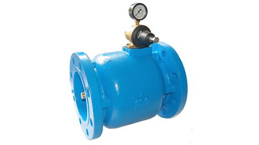
Larger pumps and mains: P04 pilot operated. The P04 is the natural choice for inline run-out protection on larger pumps. It is available in flanged sizes from DN50 to DN300, with set pressure ranges of 0.3–4 bar and 2–8 bar, and body materials including cast iron, ductile iron, bronze and stainless steel. The sustaining pilot is mounted directly on the body, with no external pilot pipework to damage or leak, and can be replaced quickly on site.
Smaller pumps and bypass lines: P09 direct acting. The P09 is a compact 316 stainless steel valve with 1/2" to 2" BSP connections and set ranges of 1–5 bar and 4–10 bar. Its balanced piston gives a fast, accurate response, making it well suited to minimum flow bypass lines and smaller process pumps. A pressure gauge indicates the sustaining pressure, which simplifies commissioning.
To apply the worked examples above: the inline valve requiring a Kv of around 20 at 4.5 bar falls within the P04 range, while the bypass valve requiring a Kv of around 3.3 at 6 bar suits a P09 in the 4–10 bar range. Confirm the final size against the valve's Kv data.
In Summary
Pumps fail at both ends of their curve: run-out at high flow and dead-heading at low flow. A pressure sustaining valve inline on the discharge prevents run-out by guaranteeing back pressure, while one in a recirculation bypass prevents dead-heading by guaranteeing minimum flow. Set it from the pump curve, size it on Kv rather than pipe size, and install it with gauges and isolation for commissioning and maintenance. Being purely mechanical, it keeps protecting the pump even when the control system does not. For a reminder of how sustaining valves differ from reducing valves, see our pressure sustaining vs pressure reducing valves guide.
Browse our full range of pressure sustaining valves, or ask our team to size a valve for your pump system. Send us the pump curve, duty point and minimum flow, and we will recommend the right valve and set pressure.