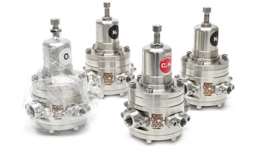
A pressure regulating valve takes a higher, often fluctuating inlet pressure and delivers a stable, lower outlet pressure to the equipment downstream. It sounds straightforward, but regulators are among the most commonly mis-sized valves in industry. A regulator chosen on pipe size alone, or on outlet pressure without considering flow, will hunt, droop or fail to deliver the pressure the process needs.
This guide sets out a six-step selection methodology, from defining the media to confirming certifications, followed by the most common selection mistakes. It applies across the full pressure spectrum, from millibar gas regulation to high pressure industrial gases at 400 bar.
Step 1: Define Your Media
Start with what is flowing through the valve, because it determines the body material, the seals and often the regulator design itself.
• Compressed air and inert gases: brass or aluminium bodies with NBR seals are usually sufficient.
• Water and general liquids: bronze, brass or stainless steel bodies; for potable water, WRAS approval is required (see Step 6).
• Steam: stainless steel or suitably rated bodies with PTFE seals capable of the temperature.
• Corrosive, high-purity or oxygen service: 316 stainless steel with compatible elastomers such as FKM (Viton) or PTFE, and oxygen-cleaned components where required.
Note the operating temperature range at the same time. Elastomers have both upper and lower limits, and a seal that suits the media chemically may still harden or soften outside its temperature range.
Step 2: Establish Inlet and Outlet Pressure
Maximum inlet pressure sets the regulator's pressure class. Use the highest pressure the regulator could ever see, including supply surges and cylinder pressure when full, not the normal operating value.
Required outlet pressure determines the spring or pilot range. Choose a range that places the set point in its middle third. A regulator set at the very bottom of its range loses sensitivity; one set near the top loses stability.
Pressure ratio between inlet and outlet affects both design and performance. Large reductions, typically more than around 10:1, can make a single-stage regulator less stable and, with gases, cause significant cooling as the gas expands. In these cases, consider two-stage regulation: two regulators in series, or a purpose-built two-stage unit. Two-stage designs also counter the supply pressure effect, where outlet pressure drifts as inlet pressure falls, which matters when regulating from gas cylinders.
Step 3: Determine the Flow Rate and Kv
Flow capacity is where most regulator selections go wrong. The regulator must pass the maximum required flow while still holding outlet pressure, and it must do so at the lowest inlet pressure it will see, because that is when the available pressure drop is smallest.
For liquids, the required flow coefficient is:
Kv = Q × √(SG ÷ ΔP)
where Q is flow in m³/h, SG is specific gravity (1.0 for water) and ΔP is the pressure drop across the regulator in bar. (Cv ≈ 1.156 × Kv if the datasheet uses imperial units.)
Worked example. A process needs 12 m³/h of water at 3 bar. Supply pressure is normally 8 bar but can fall to 6 bar at peak demand.
• At normal supply: ΔP = 5 bar, Kv = 12 × √(1 ÷ 5) ≈ 5.4
• At minimum supply: ΔP = 3 bar, Kv = 12 × √(1 ÷ 3) ≈ 6.9
Size on the worst case of 6.9. Selecting a regulator whose rated Kv puts this at around 50–80% of capacity, so roughly 9–14, leaves headroom for droop without oversizing.
For gases and steam, the sizing equations differ because the fluid is compressible and flow can become choked at high pressure ratios. Use the manufacturer's gas flow charts, or ask our team to size the regulator for you.
Step 4: Choose Self-Acting or Pilot-Operated
Self-acting (direct acting) regulators balance outlet pressure on a diaphragm or piston directly against an adjustable spring. They are compact, simple, respond quickly and need no external piping. Their limitation is droop: as flow increases, the spring extends and its force falls, so outlet pressure sags below the set point. Droop is acceptable for many applications, but it grows as flow approaches the regulator's capacity. Balanced valve designs reduce the effect of inlet pressure changes on the outlet.
Pilot-operated regulators use a small pilot regulator to sense outlet pressure and control the main valve, using line pressure to do the work. They hold the set point far more accurately across a wide flow range, with minimal droop, and are the usual choice for larger pipe sizes, high flows and applications where outlet accuracy is critical. The trade-offs are higher cost, more components, and the need for reasonably clean media to keep the pilot passages clear.
As a rule of thumb, choose self-acting for small to medium flows where some droop is tolerable, and pilot-operated for large flows, large pipe sizes or tight pressure control.
Step 5: Select Connection Size and Type
Let the Kv calculation set the regulator size, then match the connections to the pipework. Screwed BSP connections are standard in the UK for smaller regulators, NPT threads are common on equipment of North American origin, and flanged connections (EN or ASME) are used for larger sizes and higher-integrity installations. Never assume BSP and NPT are interchangeable: they have different thread angles and will leak if mixed.
Step 6: Confirm Certifications
• CE / PED: regulators for pressure equipment in the UK and EU must comply with the Pressure Equipment Directive (or the UK Pressure Equipment (Safety) Regulations) where applicable to their pressure and size.
• ATEX: regulators installed in hazardous areas, or handling flammable gases, need ATEX certification appropriate to the zone. See our ATEX resource for more information.
• WRAS: regulators in contact with potable water in the UK need WRAS approval.
• Oxygen service: regulators for oxygen require compatible materials and certified cleaning to prevent ignition.
Common Selection Mistakes
- Undersizing the Kv - Sizing at normal rather than minimum inlet pressure, or on average rather than peak flow, leaves a regulator that cannot hold outlet pressure when demand is highest.
- Oversizing to be safe - The opposite error is just as common. An oversized regulator runs barely open, close to its seat, where small movements cause large flow changes. The result is hunting, chatter, noise and rapid seat wear.
- Ignoring droop - Specifying a self-acting regulator purely on set pressure, without checking how far outlet pressure will fall at full flow, can leave downstream equipment under-supplied.
- Wrong pressure class - Rating the body for normal inlet pressure rather than the maximum possible inlet pressure, including surges or full cylinder pressure.
- Using a reducing valve where a sustaining valve is needed - If the aim is to protect a pump or hold a minimum pressure upstream, a reducing valve is the wrong device. See our guide to pressure sustaining valves and how they differ from reducing valves.
Matching the Methodology to the Our Range
We supply pressure regulating valves from ID Insert Deal and Z-Tide, covering the full pressure spectrum from millibar to 400 bar.
| Outlet pressure band | Typical applications | Regulator type | Range |
|---|---|---|---|
| Millibar | Gas burners, analysers, blanketing, low pressure instrumentation | Self-acting, large diaphragm | Low pressure (mbar) regulators |
| Up to 50 bar | Compressed air, process gases, water and general liquids | Self-acting, balanced valve; pilot-operated options | Regulators up to 50 bar |
| 220–400 bar | Industrial gas cylinders, high pressure test, gas distribution | Self-acting, piston; single and two-stage | High pressure regulators |
| Water and liquid mains | Plant water supply, washdown, process feed | Self-acting for smaller lines; pilot-operated for DN50 and above | Pressure reducing valves |
ID Insert Deal regulators are available in brass, aluminium and 316L stainless steel, with ATEX-certified versions for hazardous areas. Z-Tide reducing valves cover water and liquid service from compact direct acting designs through to large pilot-operated valves for mains supply.
In Summary
Selecting a pressure regulating valve comes down to six steps: define the media and temperature; establish maximum inlet pressure and required outlet pressure; size the Kv on peak flow at minimum inlet pressure; choose self-acting or pilot-operated according to flow and accuracy; match the connections to the pipework; and confirm the certifications the installation demands. Avoid sizing on pipe size alone, and check droop before committing to a self-acting design.
Browse our full range of pressure regulating valves, or ask our team to size a regulator for your application. Send us the media, inlet and outlet pressures and flow rate, and we will recommend the right regulator.